Dataview
LIST
FROM #Collection
WHERE file.name = this.Entry-For
Insert entry name
❗ Information
Ch.3 Topics
State Elements
- Bistable Circuit
- SR Latch
- D Latch
- D Flip-Flop
- Variations
Synchronous Sequential Logic
Finite State Machines - Moore
- Mealy
- Factored
Timing of Sequential Logic - Clock Skew
- Synchronization
Parallelism
Vocab
Edge-Triggered - Activated on the clock edge (rising or falling)
✒️ -> Scratch Notes
Part 1 - Intro to Sequential Logic
Outputs of sequential logic depend on current and prior input values
- Has memory
State - All the info about a circuit necessary to explain its future behavior - The example is the state of a password machine, has the state of incorrect password, correct password, and what number of the correct password its going on
- 3 -> 1 - > 2
Latches and Flip-Flops - State elements that store one bit of state
Synchronous Sequential Circuits - Sequential circuits using flip-flop sharing a common clock
- 3 -> 1 - > 2
- Like when your computer has a 2GHz clock
Sequential Circuit
Give sequence to events
Have memory (short-term)
Use feedback from output to input to store info
State Elements
State - Everything about the prior inputs to the circuit necessary to predict its future behavior
- Usually just 1 bit, the last value captured
State Elements: - Bistable Circuit
- SR Latch
- D Latch
- D Flip-flop
D stands for data
Part 2 - Bistable Circuit
Fundamental building block of other state elements
- Two outputs:
- No inputs
- Two inverters in a loop:
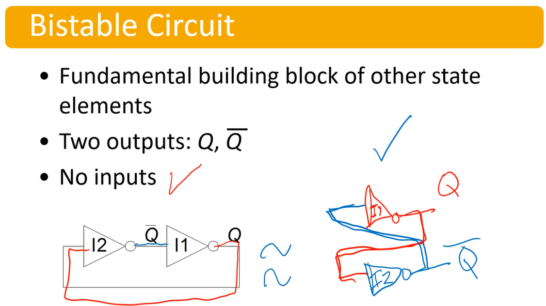
- No matter what Q is (0 or 1), it will stably store the bit
Part 3 - SR Latch
SR / RS Latch - The Set / Reset Latch
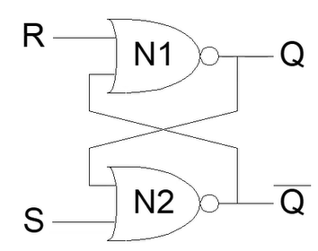
- The above are two NOR gates (0 if any inputs are 1)
| S | R | Q’ | |
|---|---|---|---|
| 1 | 0 | 1 | Set (make 1) the output |
| 1 | 1 | INVALID | Invalid, the inputs make |
| 0 | 1 | 0 | Reset (make 0) the output |
| 0 | 0 | Q | Memory state |
- In an SR latch, you must do something to avoid the invalid state S=R=1
Part 4 - D Latch
Two inputs: CLK, D
- CLK controls when the output changes
- D (the data input) controls what the output changes to
The clock cycle is enforced by ANDing the input D with the clock. When the clock is off, D will be 0 and not affect the memory.
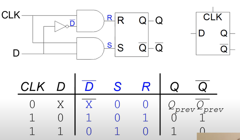
Interesting Properties - The clock cycle controls the changing of the Latch
- Avoids the invalid state of S=R=1 by making the inputs be the negation of each other
- The output of Q will equal D, when the clock is 1
Part 5 - D Flip Flop
Inputs:
- CLK
- D
Function: - Samples D on rising edge of CLK
- When CLK rises, passes D -> Q
- Otherwise, Q holds its value
Q changes only on rising edge of CLK
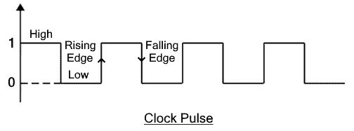
- There is a rising edge from 0->1 and a falling edge from 1->0
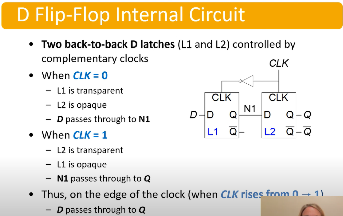
- The cycling clock only allows the value to be processed once the clock cycles. In tis circuit, that is done when CLK rises from 0->1
Flip Flop vs Latch
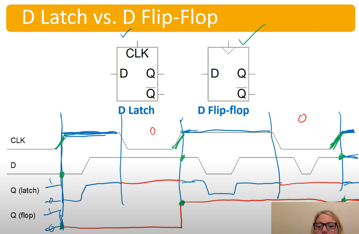
The latch will reassign itself whenever the clock is 1.
The flip flop will only assign when the clock has a rising edge
Part 7 - Intro to Synchronous Sequential Logic
Sequential Circuits - All circuits that aren’t combinational
Synchronous Sequential Logic Design
- Break cyclic paths by inserting registers
- Registers contain state of the system
- State changes at clock edge: system synchronized to the clock
- Rules of synchronous sequential circuit composition:
- Every circuit element is either a register or a combination circuit
- At least one circuit element is a register
- All registers receive the same clock
- Every cyclic path contains at least one register
- Two commons synchronous sequential circuits
- Finite State Machines (FSMs)
- Pipelines
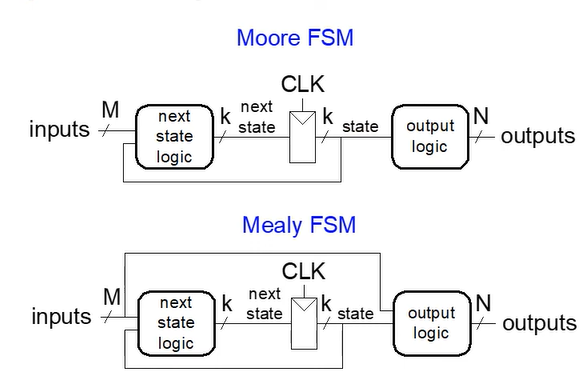
Part 8 - FSMs
Consists of:
- State Register
- Stores current state
- Loads next state at clock edge
- Combinational Logic
- Computes the next state
- Computes the outputs
- Used TWICE essentially, one block of logic to compute next state, and another for computing the output
Next state determined by current state and inputs
Two types of finite state machines differ in output logic
- Moore FSM: outputs depend only on current state
- Most common FSM
- Mealy FSM: outputs depend on current state and inputs
Part 9 - Moore FSM Ex. 1
Design Procedure
- Identify inputs and outputs
- Sketch state transition diagram
- Write state transition table (next state table) and output table
- Moore FSM: Write separate table
- Mealy FSM: Write combined state transition and output table
- Select state encodings
- Rewrite state transition table and output table with state encodings
- Write a Boolean equation for next state and output logic
| Current State | Input | Next State |
|---|---|---|
| Wake Up | 1 | Breakfast |
| Wake Up | 0 | Shower |
| Breakfast | X | Shower |
| Shower | X | Class |
| Class | X | Wake Up |
- State table
- X means dont care, could be 1 or 0 will always transition to the next state
- Next step would be to give them state encodings (00, 01, 10, 11, …)
Part 10 - Moore FSM Ex. 2
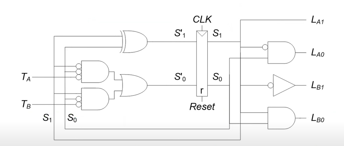
The situation is designing a traffic light, and we have two roads providing input on their level of traffic:
- Ex:
means traffic on street a - Ex:
means no traffic on street b
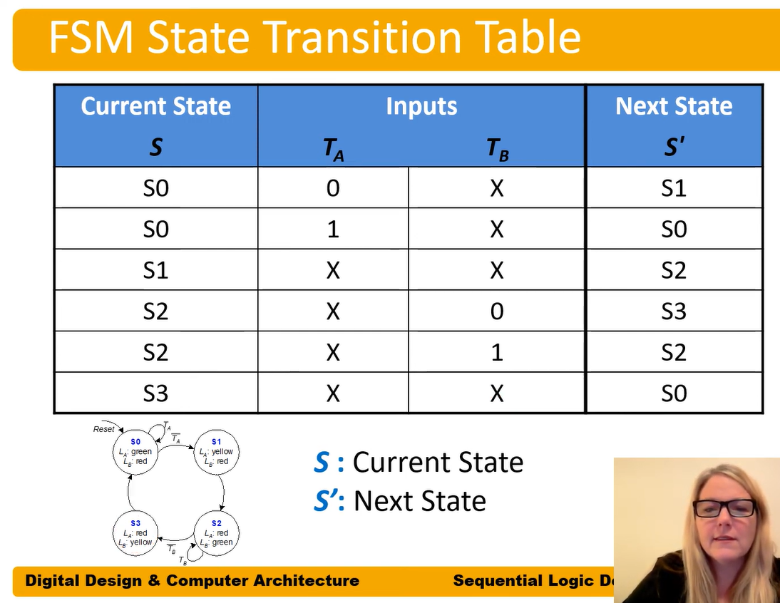
Encoding:
- S0 = 00
- S1 = 01
- S2 = 10
- S3 = 11
Encoded:
![]()
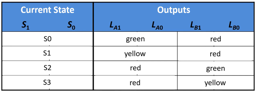
- Green = 00
- Yellow = 01
- Red = 10
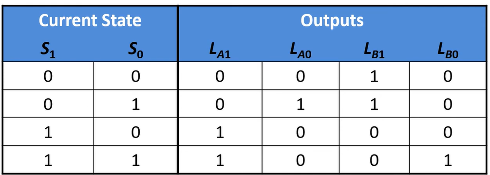
- Write logical statements like above for each L output
State Encodings:
- Binary Encoding
- What we’ve been doing, minimizes bits used in encoding
- One-hot encoding
- Only one bit per state
- Only one bit HIGH at once
- ie 0001 / 0010 / 0100 / 1000
- Requires more flip-flops, often simplifies logic
🧪 -> Refresh the Info
Did you generally find the overall content understandable or compelling or relevant or not, and why, or which aspects of the reading were most novel or challenging for you and which aspects were most familiar or straightforward?)
Did a specific aspect of the reading raise questions for you or relate to other ideas and findings you’ve encountered, or are there other related issues you wish had been covered?)
🔗 -> Links
Resources
- Put useful links here
Connections
- Link all related words