Midterm 2
Sequential Logic Circuits and the SR Flip-flop
Jump to a Latch / FF with ctrl f
SR Latch
Part 3 - SR Latch
SR / RS Latch - The Set / Reset Latch
- The above are two NOR gates (0 if any inputs are 1)
S R Q’ 1 0 1 Set (make 1) the output 1 1 INVALID Invalid, the inputs make and will both be 0 0 1 0 Reset (make 0) the output 0 0 Q Memory state Link to original
- In an SR latch, you must do something to avoid the invalid state S=R=1
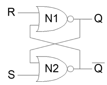
There are two SR latches, the NAND and the NOR varieties. The above is the NOR, but the NAND also exits and works pretty much backwards.
D Latch
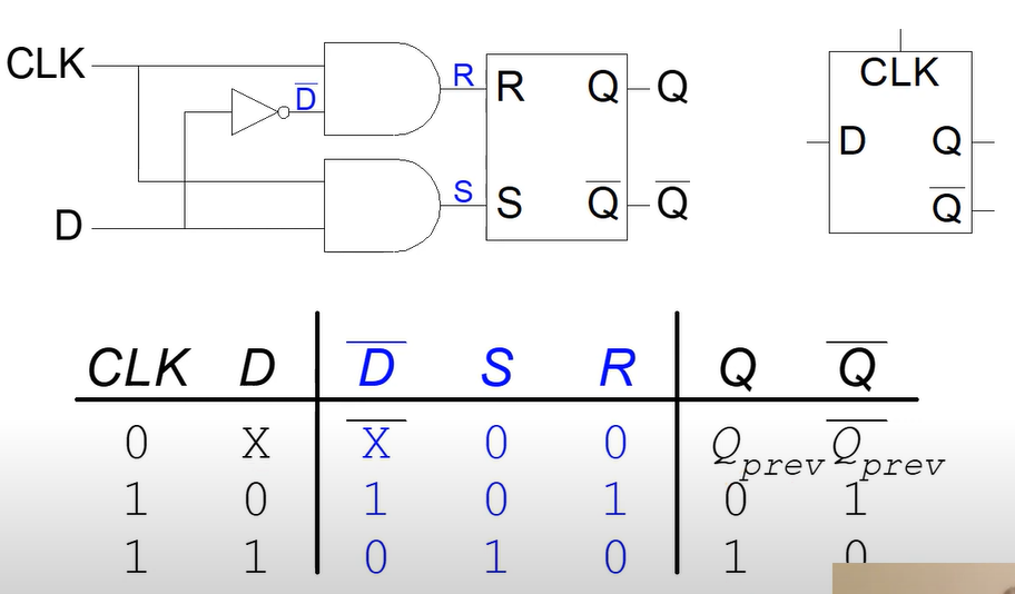
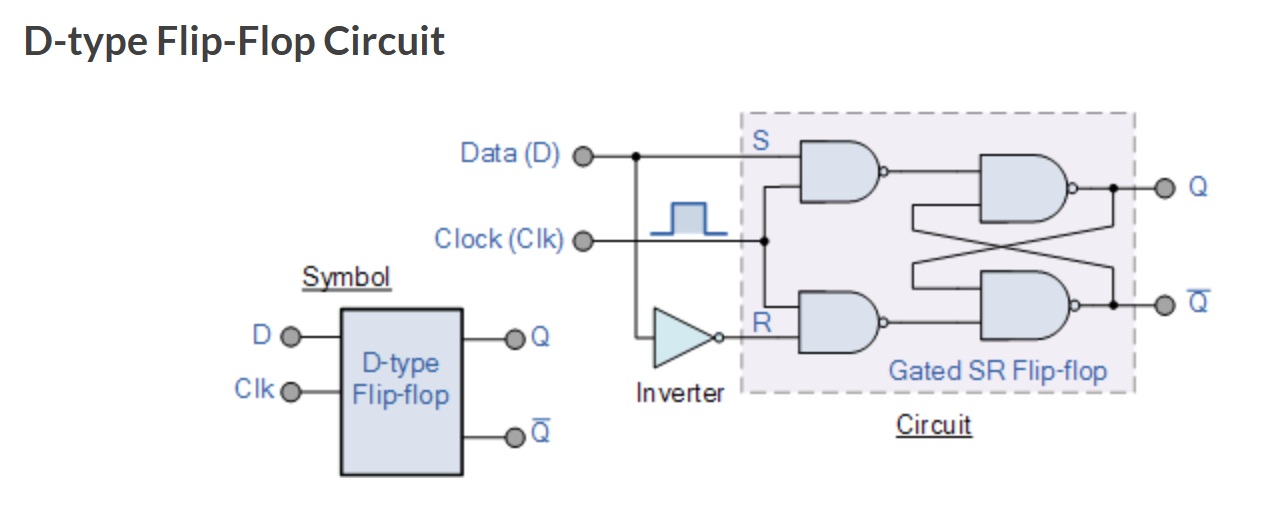
Part 4 - D Latch
Two inputs: CLK, D
Link to original
- CLK controls when the output changes
- D (the data input) controls what the output changes to
The clock cycle is enforced by ANDing the input D with the clock. When the clock is off, D will be 0 and not affect the memory.
Interesting Properties- The clock cycle controls the changing of the Latch
- Avoids the invalid state of S=R=1 by making the inputs be the negation of each other
- The output of Q will equal D, when the clock is 1
D Flip Flop
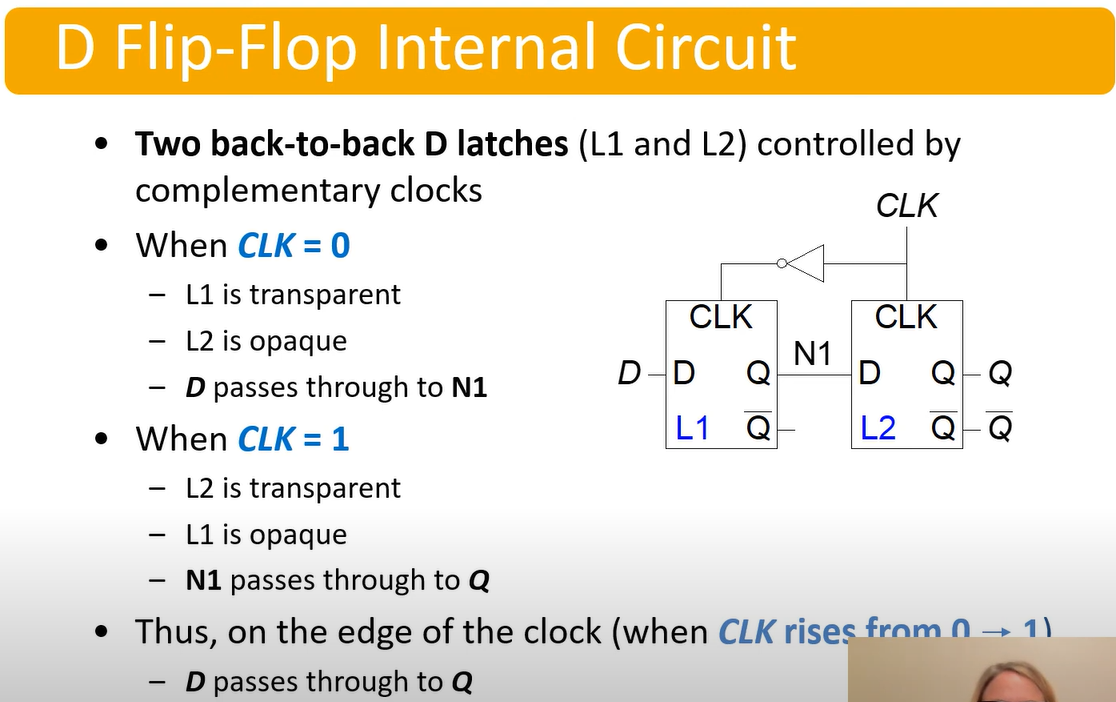
Part 5 - D Flip Flop
Inputs:
- CLK
- D
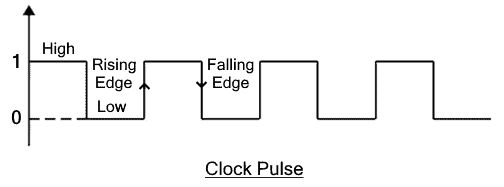
Function:- Samples D on rising edge of CLK
- When CLK rises, passes D -> Q
- Otherwise, Q holds its value
Q changes only on rising edge of CLK
- There is a rising edge from 0->1 and a falling edge from 1->0
- The cycling clock only allows the value to be processed once the clock cycles. In tis circuit, that is done when CLK rises from 0->1
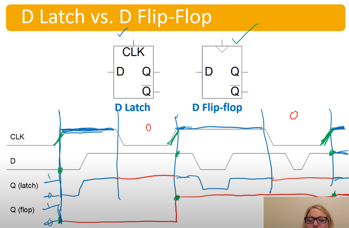
Flip Flop vs Latch
Link to original
The latch will reassign itself whenever the clock is 1.
The flip flop will only assign when the clock has a rising edge
Also look at this wiring:
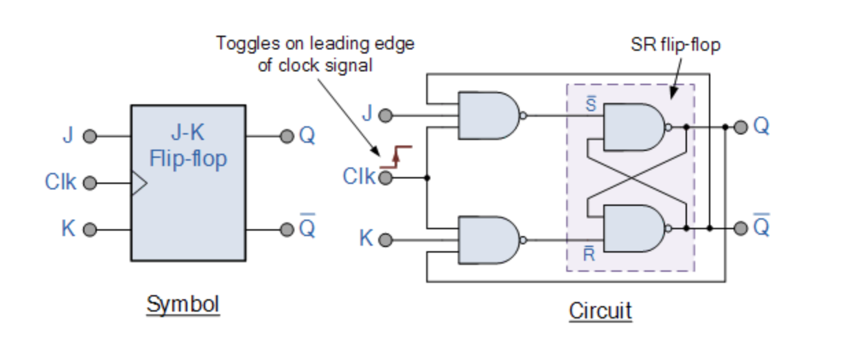
JK Flip Flop
| J | K | Q | Description |
|---|---|---|---|
| 0 | 0 | Q | Hold Memory |
| 0 | 1 | 0 | Reset |
| 1 | 0 | 1 | Set |
| 1 | 1 | Toggle (Invert Output) |
- Similar to the SR FF, with J=Set and K=Reset, but when both are 1 it isn’t invalid, it toggles Q
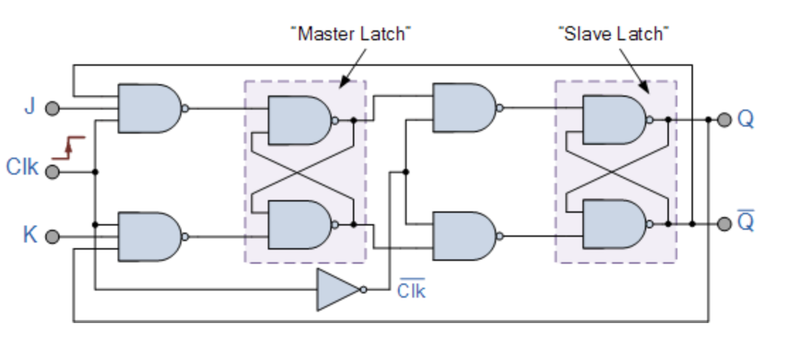
Master Slave Configuration
Two flip flops are tied together:
The input signals J and K are connected to the gated “master” SR flip flop which “locks” the input condition while the clock (Clk) input is “HIGH” at logic level “1”. As the clock input of the “slave” flip flop is the inverse (complement) of the “master” clock input, the “slave” SR flip flop does not toggle.